Support Central
If you’re reading this, you’ve likely got a TPV56PB801 power supply/LED driver board on your bench—or inside a TV that won’t turn on. Maybe you’re replacing a blown capacitor, diagnosing a backlight issue, or doing a full board swap.
Here’s the truth: Installing this board without its schematic is like driving cross-country without a map. You might get there, but the risk of frying something is high.
Let’s break down where to find the schematic, how to read its critical sections, and how to use it for a smooth installation. tpv56pb801 schematic diagram install
Mastering the TPV56PB801 schematic diagram install process transforms guesswork into precision repair. By properly obtaining, installing (digitally and physically), and interpreting the diagram, you can:
Remember: A schematic is only useful if it is installed in your workflow. Keep it on a tablet near your soldering station, annotate measured voltages directly on the PDF, and always verify your board revision before trusting the diagram. The TPV56PB801 Schematic: Your Map for a Safe
Next steps:
Have a specific TPV56PB801 issue? Visit the Badcaps.net TPV section – include your voltage readings and which revision you are using. UART/JTAG: Used for factory programming
Critical note: Do not store the only copy of the schematic on a phone that might run out of battery during repair. Always keep a printed or tablet-based backup.
The TPV56PB801 exists in several revisions:
Always match the exact REV number when downloading a schematic. Using the wrong revision can mislead you about component values, especially resistors in feedback divider networks.
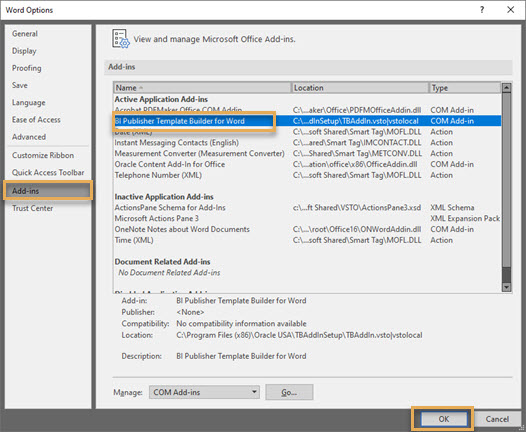
After you have installed the plugin, open Microsoft Word and click File from the menu bar at the top.
Click on Options from the left panel. From the dialog box select Add-ins on the left and select BI Publisher Template Builder for Word from the Add-ins list.
Click OK.